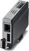
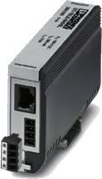
DT-TELE-SHDSL Überspannungsschutzgerät
DLS-Modem-Überspannungsschutzgerät
- Schutz für SHDSL-Telekommunikationsschnittstellen
- Schutzadapter zwischen zwei Signalpaaren über eine RJ45 (RJ12) Verbindung oder eine Schraubverbindung
- Stabiles Metallgehäuse
- Zwei SHDSL-Ports
Das DT-TELE-SHDSL Überspannungsschutzgerät erfüllt die speziellen Anforderungen einer SHDSL-Datenübertragung. Es wurde speziell für die Bereitstellung von Blitzs-, Funkstörungs-, elektrostatischen Entladungs- und transienten Überspannungsschutz zwecks maximaler Datensicherheit bei minimaler Signaldämpfung konzipiert.
Überspannungsschutz für SHDSL-Systeme
Zuverlässige Telekommunikation ist unverzichtbar in der modernen Industrie. Die in diesen Situationen eingesetzten empfindlichen Systeme arbeiten mit hohen Frequenzen bei niedrigen Signalstufen und sind über einen weiten Bereich vernetzt. Überspannungen führen hier sehr schnell zu gravierenden Ausfällen und im schlimmsten Fall sogar zu Datenverlust. Der SHDSL-Überspannungsschutz erfolgt in Form eines Adapters, der problemlos zwischen dem eingehenden Telekommunikationskabeln und einem Modem installiert werden kann. Die steckbare Schraubklemme gewährleistet eine schnelle und flexible Installation und braucht nur über das schwarze Kabel oder einen DIN-Schienenfuß geerdet zu werden.
Zwischenstecker mit Überspannungsschutz für zwei SHDSL-Telekommunikationsschnittstellen (Ports). Anschluss: RJ45 (RJ12/RJ11) und steckbare Schraubklemme (COMBICON). Alternativ aufrastbar auf Tragschiene.

Specifications
HTSUS Number:
8535.40.0000
UNSPSC Code:
39121621
ECCN:
5A991


Ambient Conditions
Ambient temperature (operation)
-40°C ... 85°C
Ambient temperature (storage/transport)
-40°C ... 85°C
Degree of protection
IP20
Protective circuit
IEC test classification
- B2
- C1
- C2
- C3
- D1
Maximum continuous voltage UC
185 V DC
Rated current
≤ 380 mA (25°C)
Operating effective current IC at UC
≤ 6 µA
Residual current IPE
≤ 4 µA
Nominal discharge current In (8/20) µs (Core-Core)
≤ 5 kA
Nominal discharge current In (8/20) µs (core-earth)
≤ 5 kA
Total discharge current Itotal (8/20) µs
10 kA
Nominal pulse current Ian (10/700) µs (Core-Core)
150 A
Nominal pulse current Ian (10/700) µs (Core-Earth)
150 A
Voltage protection level Up (core-core)
- 250 V (B2 - 100 A)
- ≤ 250 V (C1 - 500 A)
- ≤ 410 V (C2 - 5 kA)
Voltage protection level Up (core-ground)
- ≤ 580 V (B2 - 100 A)
- ≤ 580 V (C1 - 500 A)
Response time tA (core-core)
≤ 100 ns
Response time tA (core-earth)
≤ 100 ns
Input attenuation aE, sym.
- typ. 0.3 dB (≤ 2,8 MHz / 100 Ω)
- typ. 3 dB (≤ 25 MHz / 100 Ω)
Cut-off frequency fg (3 dB), sym. in 100 Ohm system
25 MHz
Capacity (core-core)
55 pF
Capacity (core-earth)
7 pF
Surge protection fault message
None
Impulse durability (conductor-conductor)
C1 - 1 kV/500 A
Impulse durability (conductor-ground)
- B2 - 4 kV/100 A
- C1 - 1 kV/500 A
- C2 - 10 kV/5 kA
VDE requirement class
- B2
- C1
- C2
- C3
- D1
Maximum continuous voltage UC
130 V AC
Pulse discharge current Iimp (10/350) µs
2.5 kA (Number of pulses category D1)
Nominal pulse current Ian (10/1000) µs (Core-Core)
100 A
Nominal pulse current Ian (10/1000) µs (Core-Earth)
100 A
Voltage protection level Up (core-core)
≤ 250 V (C3 - 100 A)
Voltage protection level Up (core-ground)
- ≤ 790 V (C2 - 5 kA)
- ≤ 300 V (C3 - 100 A)
Resistance in series
3.3 Ω 20 %
Impulse durability (conductor-conductor)
- C2 - 10 kV/5 kA
- B2 - 4 kV/100 A
Impulse durability (conductor-ground)
D1 - 1 kA
Standards and Regulations
Standards / specifications
- IEC 61643-21 2002
- IEC 61643-21
General
Housing material
Zinc die-cast
Color
silver/black
Mounting type
Connection-specific attachment plug and DIN rail, 35 mm
Design
Attachment plug for DIN rail mounting
Number of positions
4
Direction of action
Line-Line & Line-Ground/Shield
Standards for cearances and creepage distances
- IEC 60664-1
- VDE 0110-1
Connection, equipotential bonding
Connection method
Cable connection/DIN rail
Connection data
Connection method
RJ45/COMBICON
Connection method IN
RJ45 socket
Connection method OUT
RJ45 socket
Connection method IN
MC 1,5/4
Connection method OUT
MC 1,5/4
Connection technology
Screw connection
Screw thread
M2
Tightening torque
0.22 Nm
Stripping length
7 mm
Conductor cross section flexible
0.14 mm² ... 1.5 mm²
Conductor cross section solid
0.14 mm² ... 1.5 mm²
Conductor cross section AWG
28 ... 16
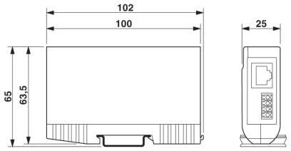
Dimensions
Height
103 mm
Width
25 mm
Depth
63 mm
Approvals
- UL Listed
- EAC
Commercial data
Packing unit
1
Weight per piece
320.0 g
Country of origin
Germany
Application Diagrams
Circuit Diagram
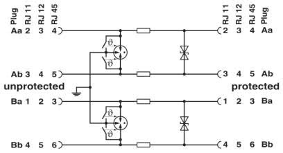
Protection Against Surge Voltage
Artikelnummer: 28015938
DT-TELE-SHDSL Surge Protector - surge protection device for two SHDSL telecommunications interfaces (ports). Connection: RJ45 (RJ12/RJ11) and plug-in screw terminal block
Power Cord: None -- Power Cord not included.