D-LAN-CAT.5-HC Überspannungsschutzgerät
CAT5/6/7 Blitz-/Überspannungsschutz für Datenleitungen
- Schutz für Datenschnittstellen
- Zuverlässige Übertragungsgeschwindigkeiten bis zu 1 Gbps
- Schutzadapter für acht Signalwege über RJ45-Verbindung (einschließlich PoE+)
- Geeignet für Hochgeschwindigkeitsdatennetze der Kategorie 6
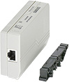
Der D-LAN-CAT.5-HC ist ein Schutzadapter, der zum Schutz der LAN-Schnittstellen und des RJ45-Kabels in die Datenleitung eingefügt wird.
Überspannungsschutz für Informationstechnologie
Zuverlässige Daten sind unverzichtbar in der modernen Industrie. Die in LAN eingesetzten empfindlichen Systeme arbeiten mit hohen Frequenzen bei niedrigen Signalstufen und sind über einen weiten Bereich vernetzt. Überspannungen führen sehr schnell zu gravierenden Ausfällen und im schlimmsten Fall sogar zu Datenverlust. Datenleitungs-Überspannungsschutzgeräte wurden speziell konzipiert, um Ihre Investitionen in kostspielige verdrahtete, drahtlose und PoE-Geräte zu schützen.
Schutz für Hochgeschwindigkeitsdaten
Wenn Sie effektiven Blitz-, Funkstörungs-, elektrostatischen Entladungs- und transienten Überspannungsschutz für Hochgeschwindigkeitsdatenübertragungen benötigen, bietet Ihnen das DT-LAN-CAT.5-HC universalen Schutz ohne Beeinträchtigung des Signals bei Netzwerkgeschwindigkeiten bis zu 1 Gbps.
Geeignet für folgende Umgebungen
- 100/1000/10G-Base-T
- Power over Ethernet (PoE+) “Mode A” und “Mode B”
- TOKEN Ring
- ISDN
- DS1
RJ45-Zwischenstecker mit separater Erdungsleitung und Erdanschlussrastfuß für Tragschienen NS 35 DIN.
Specifications
HTSUS Number:
8535.40.0000
UNSPSC Code:
39121621
ECCN:
5A991
Ambient Conditions
Ambient temperature (operation)
-40°C ... 85°C
Ambient temperature (storage/transport)
-40°C ... 85°C
Degree of protection
IP20
Protective circuit
IEC test classification
- B2
- C2
- D1
- C1
Maximum continuous operating voltage UC
± 5 V DC
Maximum continuous voltage UC(line-line)
± 5 V DC (± 57 V DC/PoE+)
Rated current
≤ 1.5 A (25°C)
Operating effective current IC at UC
≤ 600 µA
Nominal discharge current In (8/20) µs (line-line)
350 A
Nominal discharge current In (8/20) µs (line-ground)
2 kA
Pulse discharge current Iimp (10/350) µs (line-earth)
1 kA
Total discharge current ITotal (8/20) µs
8 kA
Nominal pulse current Ian (10/700) µs (line-line)
≤ 25 A
Nominal pulse current Ian (10/700) µs (line-earth)
≤ 100 A
Output voltage limitation at 1 kV/µs (line-line) spike
- ≤ 25 V
- ≤ 90 V (PoE)
Output voltage limitation at 1 kV/µs (line-earth) spike
≤ 750 V
Residual voltage at In (conductor-conductor)
- ≤ 35 V
- ≤ 110 V (PoE)
Residual voltage at In (conductor-ground)
- ≤ 35 V
- ≤ 850 V (PoE)
Voltage protection level Up (line-line)
- ≤ 20 V (B2 - 1 kV/25 A)
- ≤ 90 V (B2 - 1 kV/25 A - PoE)
- ≤ 35 V (C1-700 V/350 A)
- ≤ 110 V (C1-700 V/350 A-PoE)
Voltage protection level Up (core-ground)
- ≤ 700 V (B2 - 4 kV/100 A)
- ≤ 850 V (C2 - 4 kV/2 kA)
Response time tA (line-line)
≤ 1 ns
Response time tA (line-earth)
≤ 100 ns
Input attenuation aE, sym.
- ≤ 0.5 dB (100 MHz/100 Ω)
- ≤ 1 dB (100 MHz/100 Ω/Link Class E)
Near-end crosstalk attenuation
- typ. 63 dB (1 MHz/100 Ω/Link Class E)
- typ. 43 dB (16 MHz/100 Ω/Link Class E)
- typ. 30 dB (100 MHz/100 Ω/Link Class E)
- > 40 dB (100 MHz/100 Ω)
Cut-off frequency fg (3 dB), sym. in 100 Ohm system
> 250 MHz
Capacity (core-core)
typ. 15 pF (f= 1 MHz / VR= 0 V)
Capacity (core-earth)
typ. 5 pF (f= 1 MHz / VR= 0 V)
Impulse durability (conductor-conductor)
- B2 - 1 kV / 100 A
- C2-4 kV / 2 kA
- D1 - 1kA
Impulse durability (conductor-ground)
- B2 - 4 kV/100 A
- C2 - 4 kV/2 kA
- D1 - 1 kA
General
Color
gray/black
Housing material
PC+ABS
Flammability rating according to UL94
V-0
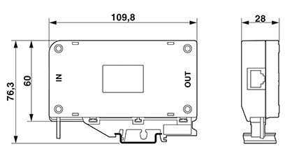
Dimensions
Height
109.8 mm
Width
28 mm
Depth
76.3 mm
Standards and Regulations
Standards / specifications
- VDE 0110-1 / IEC 60664
- IEC 61643-21/A1 2008
- EN 61643-21/A1 2009
- IEC 61643-21 2000
- GB/T 18802.21 2004
Environmental Product Compliance
China RoHS
Environmentally friendly use period: unlimited = EFUP-e
Approvals
- UL Listed
- EAC
Commercial data
Packing unit
1
Weight per piece
178.0 g (including packaging)
25.0 g (excluding packaging)
Country of origin
CN
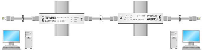
Application Diagrams
Data Line Surge Protector Application Diagram
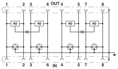
Circuit Diagram
Protection Against Surge Voltage
Artikelnummer: 28007638
D-LAN-CAT.5-HC - surge protection device for Ethernet Transmission speeds up to 1G. Connection: dual RJ45
Power Cord: None -- Power Cord not included.